Plain skin
The baseline: a continuous 0.8 mm skin without the reinforcing rib network.
How much useful coupling does the skin provide by itself?
 Book a call ↗
HERON BEAK / BUILD IN PUBLIC
Two opposing finger pairs. A thumb that can join either side. And a tactile surface we want to print ourselves.
We have the gripper design, the sensor CAD and three TPU experiments ready to try. What’s missing is access to a suitable printer to turn them into hardware.
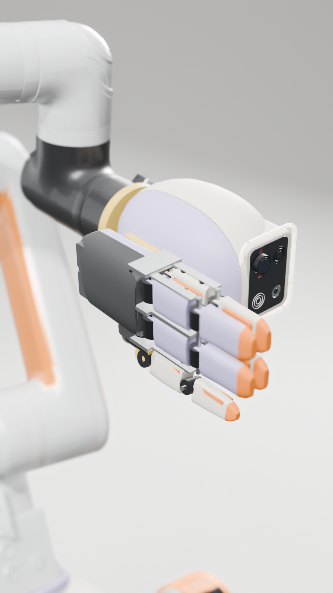
Think of the two jaws of a conventional gripper split into four fingers: two on one side, directly opposed by two on the other. The fifth finger is a thumb that swivels to work with either pair.
That is the idea behind Heron’s beak. The aim is to keep a familiar opposing grip while exploring more adaptable contact. The thumb’s useful range, clearances and control still need physical testing.
Where the funny bird came from ↗We want the finger pad itself to become part of the sensor.
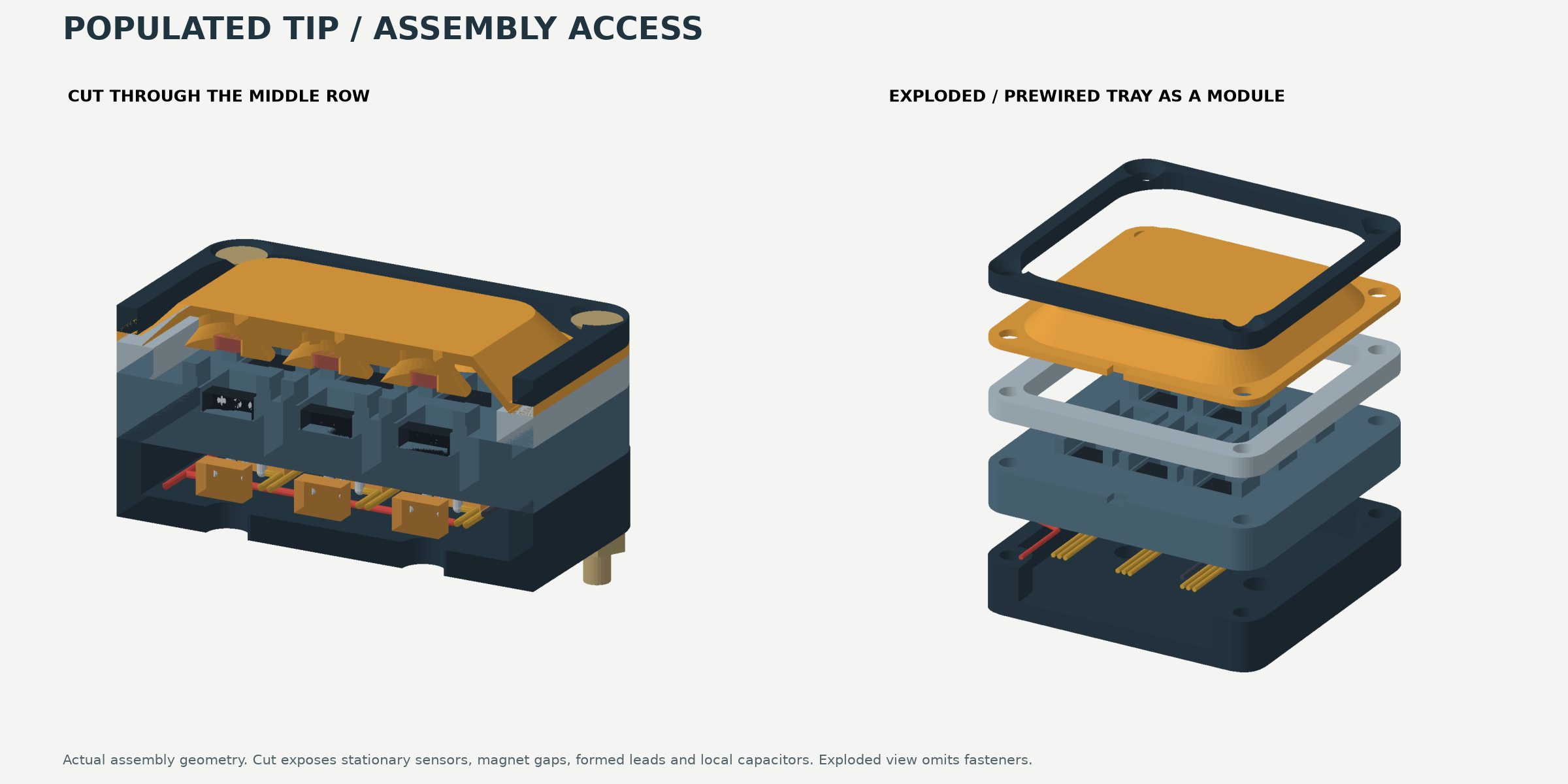
A replaceable TPU cap holds nine small magnets above nine stationary Hall sensors. Contact deforms the shared skin and moves the magnets. The sensors register changes in magnetic field across the array.
The useful signal is the combined pattern, not nine independent pressure pixels. Mechanical coupling spreads a contact through the cap; magnetic coupling means each sensor also sees neighbouring magnets.
A calibration experiment must connect those nine readings to known contact positions and loads. Until that happens, they are magnetic readings, not a validated force measurement.
R1 bench cartridge: 34 × 34 mm footprint · 24 × 24 mm contact face · 3 × 3 sensor grid at 8 mm pitch. These are nominal CAD dimensions.
The first comparison keeps the outer interface and sensor positions fixed. Only the structure inside the TPU cap changes.
The baseline: a continuous 0.8 mm skin without the reinforcing rib network.
How much useful coupling does the skin provide by itself?
A regular network of 0.8 mm-wide ribs adds structure between the magnet locations.
How do repeatability, deflection and signal spread change?
Mixed 0.8 / 1.2 mm rib widths and two diagonal links create different stiffness paths.
Can nearby contact positions produce more distinguishable patterns?
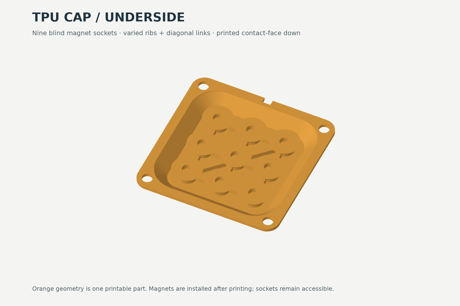
After that baseline, we can vary print orientation, wall thickness and material hardness one factor at a time. The first material is TPU 95A. We need to measure hysteresis, creep, return to zero and cap-to-cap variation, as well as the fit of the small magnet sockets. A beautiful render cannot answer those questions.
The first build is a standalone tactile cartridge. Fitting it to Beak is a later step, once its size, attachment, wiring and measured response make sense.
We have nominal CAD, printable meshes and simplified synthetic contact experiments. We have not yet printed, assembled or calibrated this R1 module. The synthetic model suggests questions worth testing; it does not establish force accuracy, tactile resolution or reliable slip detection.
The existing mug and egg grasp films are contact simulations with an earlier sensing concept. They show the direction of the gripper work, not physical validation of the new Hall array.
Check real magnets, sensor packages, sockets and clamping surfaces before a full build.
Check polarity, baseline, clipping, noise and acquisition timing with controlled magnet motion.
Apply known positions and loads. Repeat load/unload cycles and test positions kept out of calibration.
Measure interference from steel and motors, then decide how the cartridge should fit the hand.
THE PROJECT IN 43 SECONDS
The gripper concept, the magnetic tactile experiment and the first physical tests we want to make. Original rendered hardware and labelled explanatory animation.
Silent, with on-screen text. Open the short ↗
A CONCRETE WAY TO HELP
Can you lend or sponsor a machine that prints TPU reliably?
I’m building this in public as The Tech Storyteller. Right now I don’t have the right printer available for these tests. An open-box, refurbished, demo or previous-generation machine could move the project forward.
The immediate job is modest: small TPU 95A caps, thin ribs, repeatable magnet sockets and rigid PETG fixtures. Material handling and reliable small features matter more here than a headline speed number. I’m new to hands-on 3D printing and will document that learning honestly.
In return, we can agree on a useful build story: the first prints, failed revisions, sensor bring-up and what the measurements actually show. We’ll discuss coverage, timing, shipping and return arrangements together.
If you’re a creator with an idle test machine, or the person who handles creator partnerships at a printer company, I’d love to hear from you. An introduction helps too.
Let’s put it on the bench ↗Media kit ↗Gripper architecture and original rendered footage: Heron design work, October 2026. Magnetic tactile cartridge: Nine-channel tactile fingertip R1, 26 October 2026. This page connects those development stages; it does not claim they are already integrated.
The TI DRV5055 measures magnetic flux density with an analogue output. The proposed readout uses two MCP3208 ADCs and a Raspberry Pi Pico. Force and contact position require mechanical testing and calibration of the assembled system.
All hardware imagery here is original CAD/rendered design material. Diagrams illustrate the proposed mechanism. No measured load rating or sensing performance is claimed. Project status checked 1 November 2026.
Also on the bench: the Onebox sensor →