
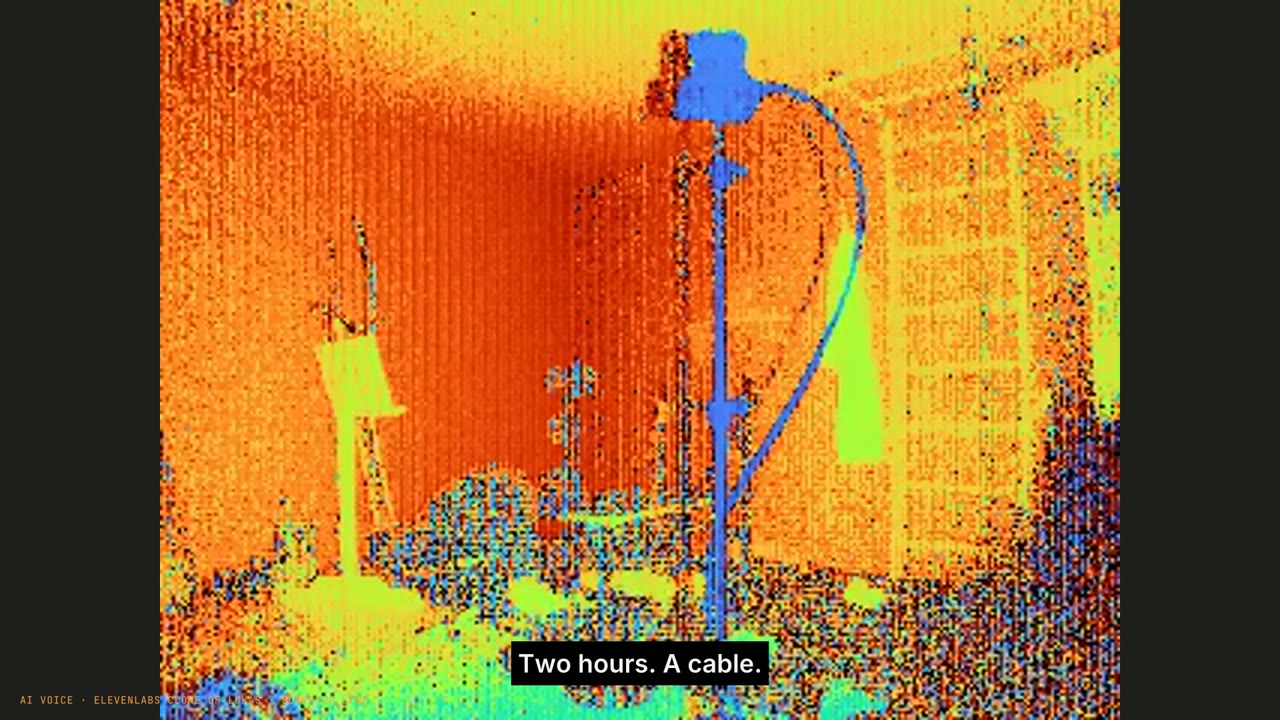
An under-$100 RGB + ToF + IMU concept is evaluated with a custom simulator, then an epc660-class engineering sample is brought up beside a Pi camera. A cable causes two hours of brown-outs. Calibration improves 12.7 to 4.56 pixels but misses the <4 px target; a 30-second map motivates a shared clock, IMU and factory calibration.
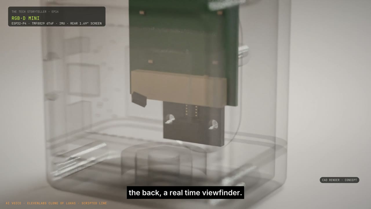
I started with a product-shaped question: could we make a small RGB + depth + IMU sensor for the home lab, with an initial target below $100? The episode ends with real points from separate sensors, not the integrated box in the render.
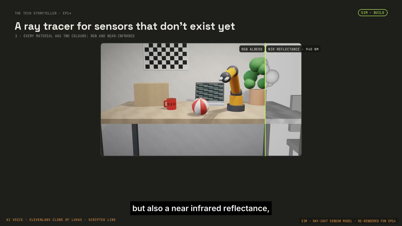
First, compare the sensing routes.
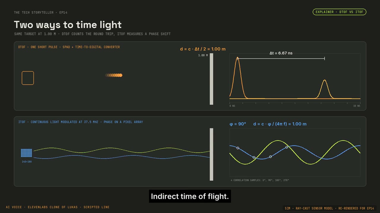
We built our own ray-cast comparison of direct ToF, indirect ToF and stereo in scenes with hands and nearby objects. The denser iToF model had an advantage in hand coverage; sparse dToF offered a different per-point trade-off, and a plain white bench challenged stereo. These are simulation results under our assumptions, not a product benchmark.
Then, keep the hardware alive.
The available epc660-class engineering sample needed protocol work and an SDK build on Apple Silicon. Starting measurements repeatedly caused brown-outs. A cable swap resolved the immediate problem after roughly two hours. Only then could we spend our time arguing with the geometry.
Paired with a Pi camera, the sensor gave us a registration problem that automatic feature matching did not solve. The landmark loop improved the reported error from 12.7 to 4.56 pixels. Our later held-out review measured 4.56 px RMS and a 6.54 px maximum at 640 × 480. The acceptance thresholds were below 4 px RMS and below 6 px for every held-out landmark. The candidate failed and remained provisional.
A useful failure becomes a specification.
A 30-second recording and voxel map made the next design requirements concrete: a stable sensor mounting, a shared clock, an IMU and calibration that belongs to the device. The film documents an actual bring-up and an unfinished calibration. It does not establish hardware synchronisation, a validated product price or a finished one-box sensor.
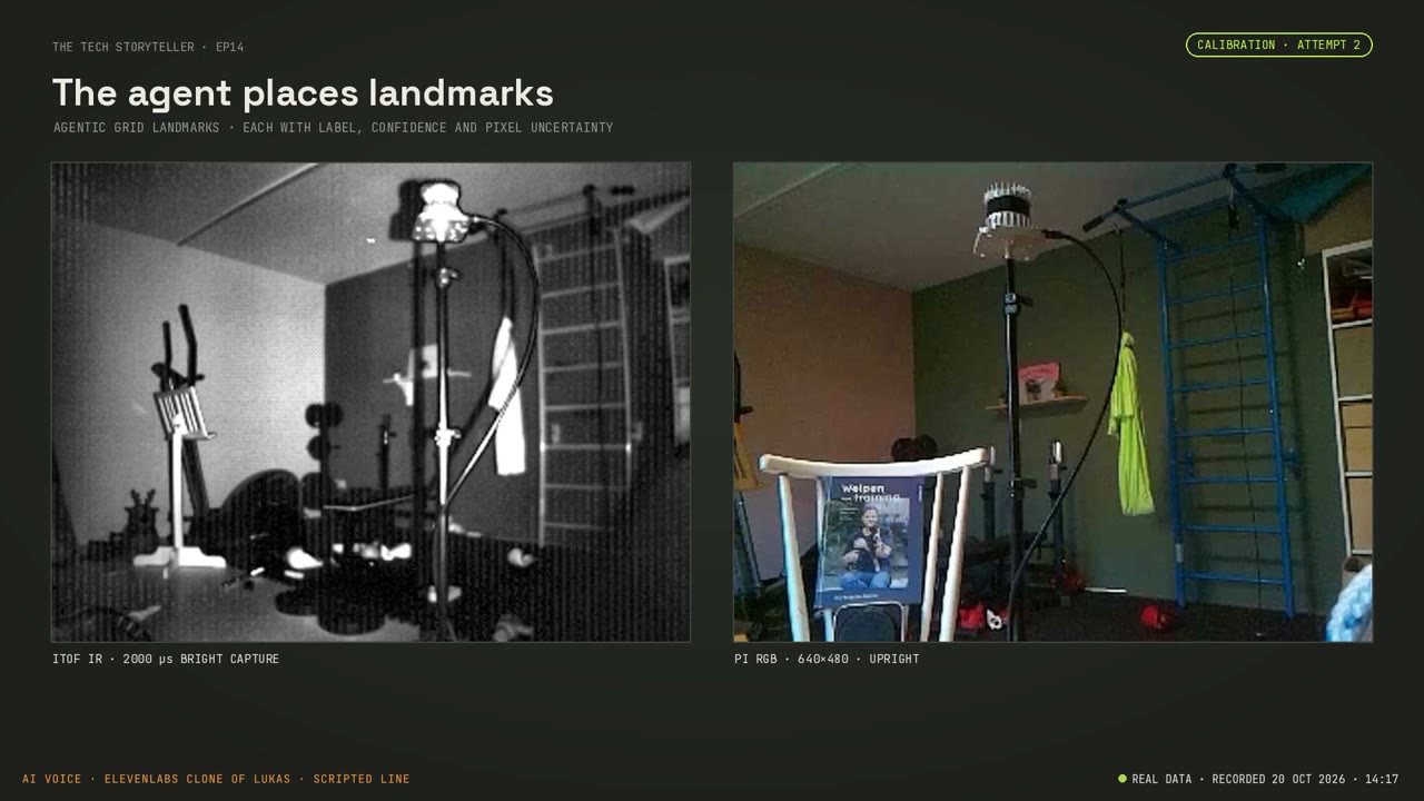
The longer cross-episode sensor story connects this attempt to the Ouster experiments, the next day’s bent-wall investigation and the Mini-X architecture.
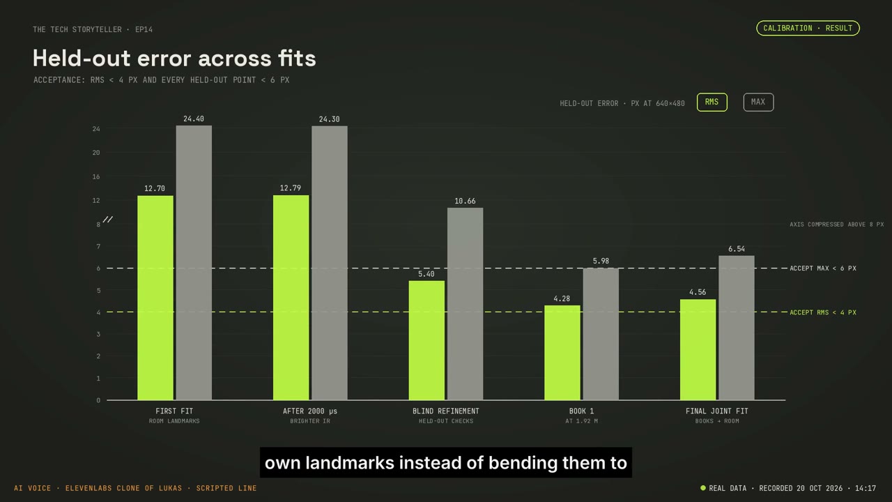
Scope of this episode: Separate demonstrated sensors; one-box is a concept; under $100 is a target; provisional calibration.
Based on the published episode and its production record. YouTube publication verified 22 October 2026. Stills are extracted from the released episode. Captions distinguish recorded evidence, reconstruction, simulation and illustrative material.