
ON THE BENCH
Real sensor. Separate camera.
An epc660-class 320 × 240 engineering sample beside a Pi RGB camera. Live depth, recordings and calibration tests.
ON THE DRAWING BOARD
One integrated device.
Pi rig, Mini, Mini-i and Mini-X concepts. The shared clock, custom PCB and finished enclosure still need hardware validation.
Why build Onebox?
In Episode 3, a cheap Pi camera and the Ouster OS0 gave us a coloured point cloud—and a person’s colours projected onto the wall behind them. In Episode 10, a plausible wall alignment could still put the camera in the wrong physical place. Spatial alignment, timing and visibility were separate problems.
Onebox is the attempt to stop rebuilding that integration every time: a rigid RGB/depth relationship, a shared timebase, an IMU and calibration that stays with the device. A wrist or chest-mounted recorder should be as useful as a robot’s eye. The original sub-$100 ambition remains an exploratory target; it is not a validated bill of materials or a price for Mini-X.
The design changed as the question changed.
These are related design studies, including two different depth-sensor routes. The compact Mini and the larger Mini-i explore different compromises; the pictures do not represent a sequence of manufactured prototypes.
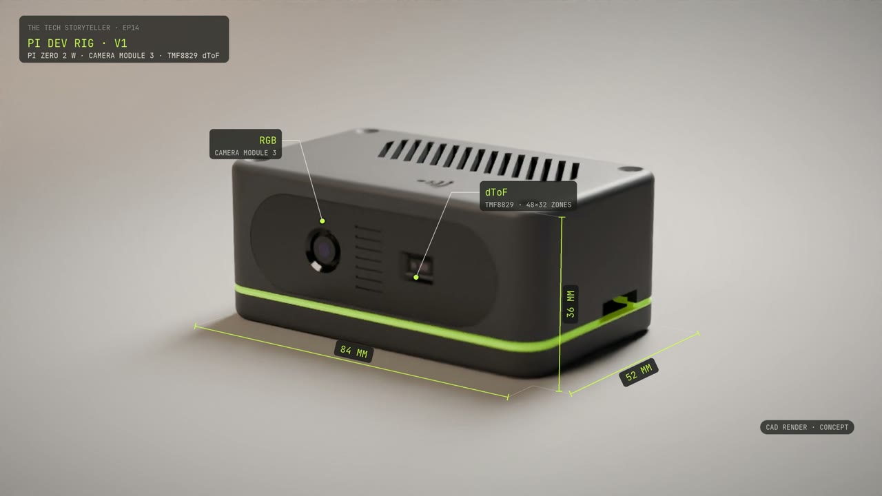
01 / Pi development rig: make the pieces fit.
The first enclosure study puts a Pi Zero 2 W, Camera Module 3 and TMF8829 direct-ToF sensor into an 84 × 52 × 36 mm envelope. It explores where the lenses, boards and connectors could go while retaining familiar development hardware.
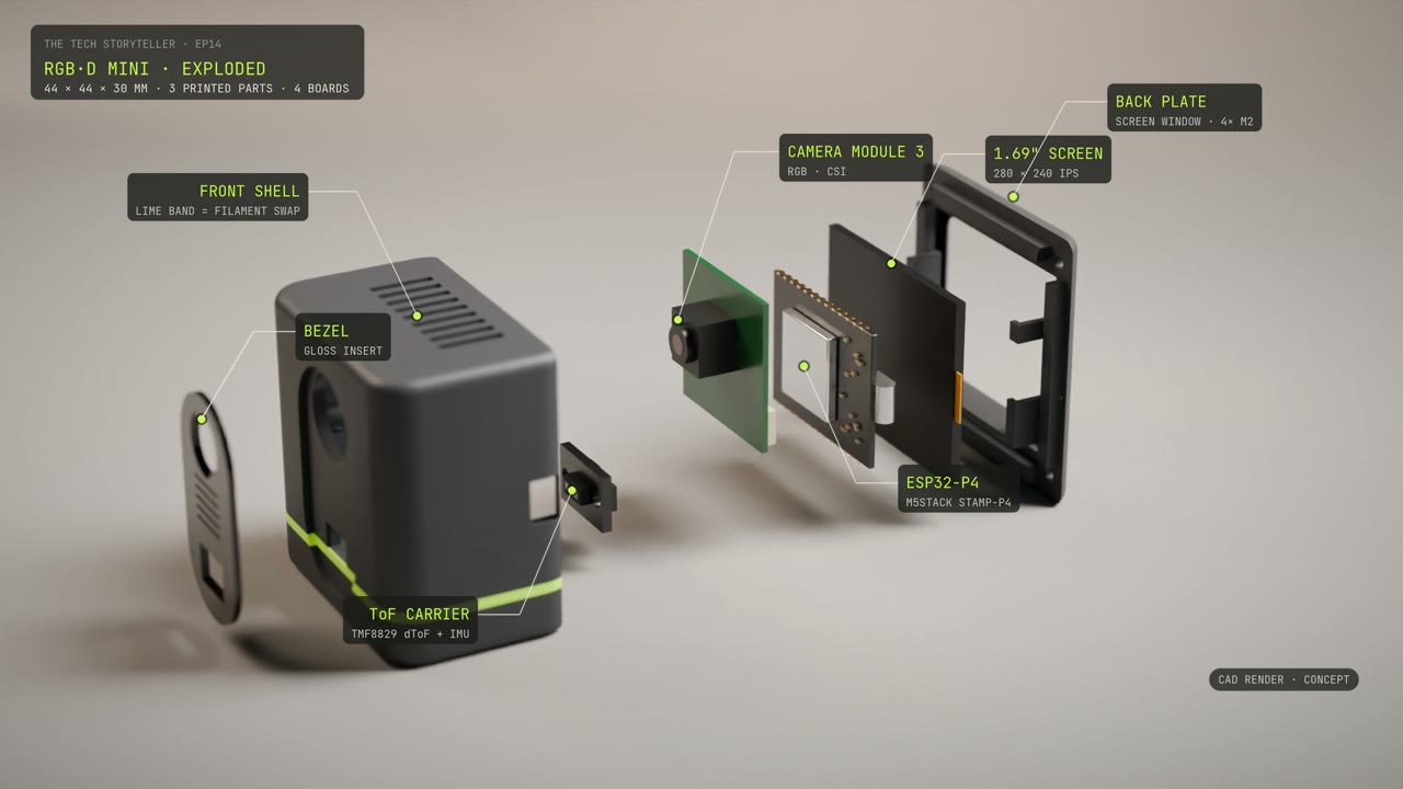
02 / RGB·D Mini: smaller compute, smaller package.
The 44 × 44 × 30 mm Mini replaces the Pi layout with an ESP32-P4 module, a TMF8829/IMU carrier and a rear 1.69-inch display. The exploded film exposes the packaging problem: several boards, the camera, connectors and the display all compete for the same small volume.
A later 42 × 42 mm “one-board” study proposes shared timing, power, USB-C and the sensor interfaces. That drawing is a functional proposal. It is not a routed or fabricated PCB, and synchronisation has not been demonstrated on it.
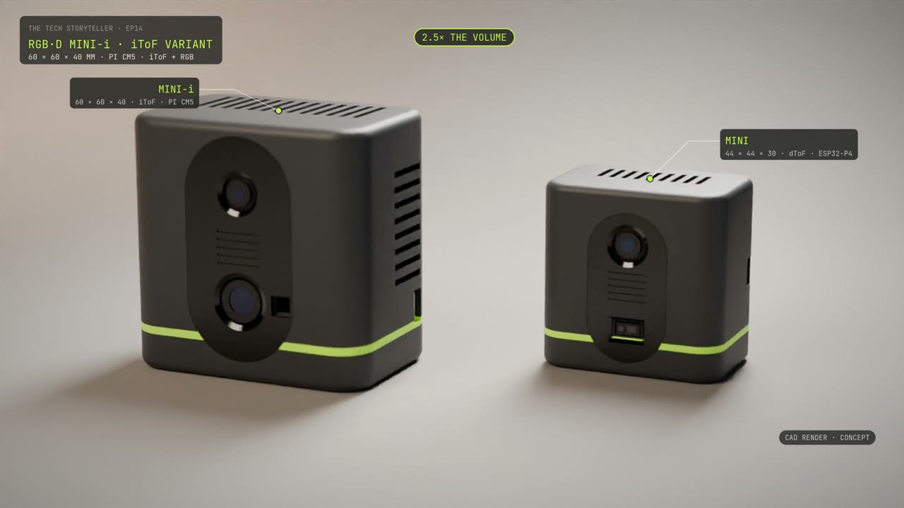
03 / Mini-i: a parallel route to denser depth.
The iToF variant grows to 60 × 60 × 40 mm and uses a Pi CM5. Its M12 depth lens sits below the RGB camera, with a separate illumination window, internal baffle and space for cooling. More depth samples change the optics, compute and enclosure together.
Which chip earns its place?
Episode 14 compares the measurement routes in a ray-cast simulator before returning to hardware. The TMF8829 model uses 48 × 32 zones; the iToF model initially uses 240 × 180. In those particular scenes, iToF gives 35–51 times as many correct hand points, while dToF’s valid individual points are more accurate. Those are simulation results, not a measured hardware ranking.
| Route | What it offers | What must be proved |
|---|---|---|
| TMF8829 / dToF | Compact close-range depth; the route drawn in the Pi rig and Mini. | Whether sparse sampling preserves enough hand and object detail on real hardware. |
| epc660-class / iToF | A real 320 × 240 engineering sample available for bring-up. | Depth accuracy across distance, material, exposure and the image field. |
| ESP32-P4 | The compact Mini compute proposal; also explored for Mini-X. | For Mini-X, simultaneous RGB MIPI CSI and depth DVP capture, bandwidth, timing and thermal behaviour. |
| Pi CM5 | The larger Mini-i architecture, with cooling room in the CAD layout. | Power, heat, acquisition reliability and whether the larger package suits the intended mounting. |
The real prototype starts with a cable.
The hardware available for the first test was an iToF engineering sample and a separate Pi camera. Getting that sample to stream meant working through its protocol and building the SDK on Apple Silicon. It connected, then browned out when a measurement began. Roughly two hours later, a cable change got us to the first live depth view.
A live stream only answers the first question. The next ones are whether every frame is valid, whether the timestamps mean what we think they mean, and whether the camera and depth sensor agree when something moves.
RGB and depth: closer, but not accepted.
Automatic feature matching failed. The next attempt used corresponding landmarks in the recorded infrared and RGB views. The reported alignment error improved from 12.7 to 4.56 pixels RMS; the held-out maximum was 6.54 pixels.
The acceptance thresholds were below 4 pixels RMS and below 6 pixels for every held-out point. We missed both, so the candidate calibration was not accepted or applied. Some landmarks were manually localised and the Pi intrinsics were provisionally reused. A 30-second recording and voxel map made the requirements for the integrated device more concrete: rigid mounting, current intrinsics, verified transforms and a shared clock.
Then a straight wall came back bent.
In Episode 15, the iToF wall bowed by roughly 12–14 cm across a 4.5 m wall. The Ouster reference stayed straight. Reducing noise could make the cloud look better without correcting the geometry.
Longer integration reduced raw jitter from 85 to 28 mm and filtered jitter from 65 to 6 mm in the exposure test, but 8.9% of samples reached the ADC rail. The receiver also needed packet-length checks, rejection of corrupted frames and byte resynchronisation.
A correction fitted to one wall reduced its plane RMS from 4.45 to 1.84 cm at about four metres. It did not establish accuracy at other distances. Lens spill, mixed pixels and cyclic depth error remain candidate explanations to test. This is why the dToF alternative remains open.
04 / Mini-X: the idea becomes Heron’s eye.
The parallel Heron design work expands Onebox into a proposed 62 × 46 × 36 mm multimodal head module. RGB and iToF are joined by MLX90640 thermal, A121 radar, an IMU and stereo microphones. The dimensions come from the design discussion; component fit and board layout are still provisional.
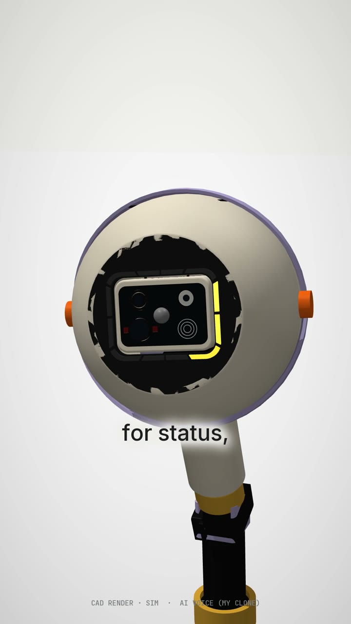
The extra channels make compute and interface selection more consequential. Before a Mini-X PCB is committed, the proposed ESP32-P4 configuration needs to demonstrate concurrent CSI RGB and DVP depth acquisition. Optical alignment, illumination, temperature calibration, power and enclosure assembly need physical tests too.
Explore Heron’s design experiments and three 9:16 films →
What the next prototype needs to prove.
- Reliable capture. Survive measurement load, reject corrupt packets and preserve trustworthy timestamps.
- Depth beyond one wall. Run a range sweep and a spill test, then compare the dToF alternative on the same close-range tasks.
- Alignment that survives a new scene. Measure current intrinsics and validate on held-out captures, motion and repeat mounting.
- Integration before miniaturisation. Prove concurrent interfaces and shared timing on the bench, then turn the board and enclosure studies into hardware.
The design revisions explain what I want to build. The prototype recordings explain what the next revision has to earn.
Sources: original Episode 14 CAD films and published Episodes 3, 10, 14 and 15; the calibration review; Mini-X design discussions; an earlier Heron launch film. All eight media panels use original video material. The real recordings show sensor output and analysis; the enclosure and robot views are labelled design studies.