
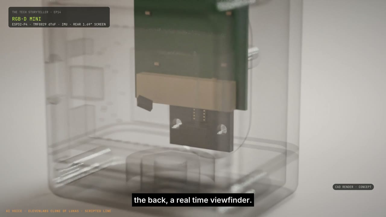
I wanted one box I could put on a robot, plug in, and get colour and depth that already agreed. After several episodes of calibration, a camera on one cable and a depth sensor on another started to feel like the wrong place to begin.
That idea now runs through the series: the Ouster and cheap camera in Episode 3, the phone viewer in Episode 4, the office twin, the iPhone calibration in Episode 10, and the small ToF experiment in Episodes 14 and 15. Each attempt exposed a different part of the same problem.
State of the build · 22 October 2026. The working bench experiment uses separate sensors. The integrated RGB + depth + IMU device, the Mini-X enclosure and its extra sensing channels are design studies. The sub-$100 figure belongs to the original design ambition, not a validated price for the expanded Mini-X.
A coloured point cloud is a very convincing trap.
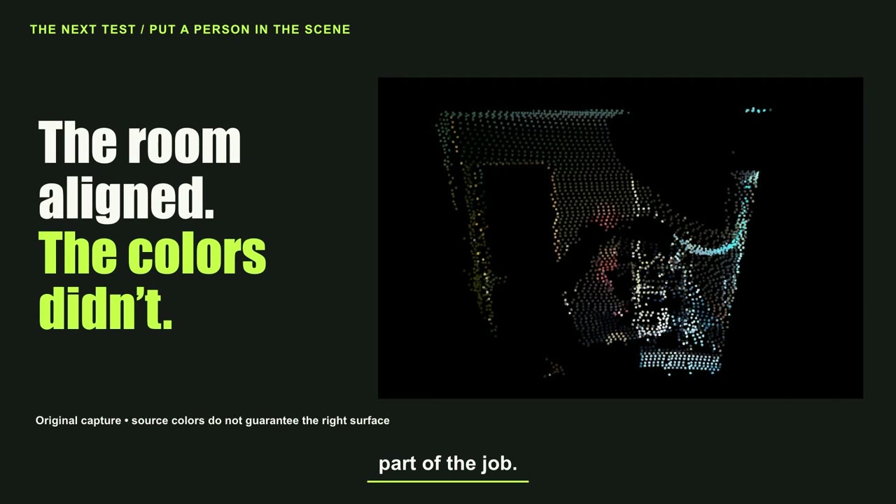
In Episode 3, I paired a roughly $5 Pi camera with the Ouster OS0. A checkerboard on my MacBook, manual feature matches and repeated fits brought selected room boundaries closer together. The mean of seven selected boundary medians fell from about 13.5 to 4.2 pixels. Then I sat in the scene, and my colours appeared on the wall behind me.
The failure forced us to separate three jobs: spatial alignment, observation timing, and camera visibility. A real wall point must not inherit the colour of a shirt that happens to occupy the same camera pixel. Deleting the wall to make the image look cleaner is not a calibration fix.
Episode 4 added another distinction. We could send Ouster data through the Mac to an old Samsung S10. That made a working viewer, not a phone that knew its position in the map. Pose jumps, an IMU compatibility problem and an Ethernet adapter disappearing from the Mac made the plumbing part of the story.
The room reconstruction and robot-dojo episodes made the stakes more concrete: the map was becoming a place where simulated robots would act. In Episode 10, an iPhone alignment looked plausible on flat walls while putting the camera in the wrong physical position. A small residual could still reward the wrong explanation. The camera intrinsics remained estimated.
Choose the measurement before choosing the chip.
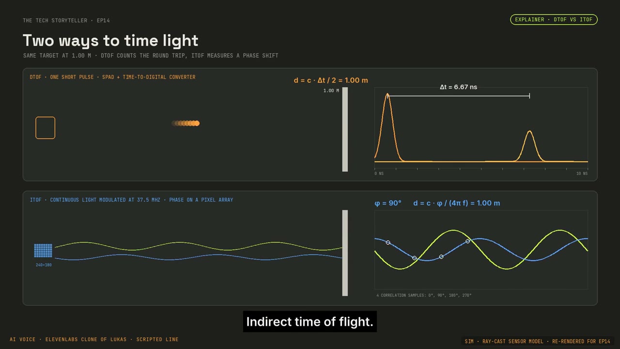
For the small sensor, I wanted to see hands and nearby objects. A dense-looking room scan was not enough. We built a ray-cast simulator with chest-mounted and tabletop scenes, then compared direct ToF, indirect ToF and stereo against known scene geometry.
| Route | Why it entered the experiment | The unresolved trade-off |
|---|---|---|
| dToF · TMF8829 | A 48 × 32-zone candidate for close-range sensing. In our model, the individual valid points were accurate. | Sparse sampling can miss small hand features. The physical comparison is still to come. |
| iToF · epc660 class | More spatial samples on hands. The simulator initially used 240 × 180; the real engineering sample provides 320 × 240. | Depth bias, mixed returns and optical effects need measurement. More pixels do not settle accuracy. |
| Stereo | A familiar RGB-D route and a useful comparison in the same scenes. | Our plain white bench exposed the model’s dependence on visible texture. |
In those particular simulated scenes, iToF produced 35–51 times as many correct hand points as the sparse dToF model; the stereo model fell to 62% valid coverage on the plain bench. These are results of our scene and noise models. They are a reason to run a bench test, not a measured ranking of commercial sensors.
The practical next step was the hardware already available: an epc660-class iToF engineering sample and a Pi camera. That let us test the integration problem before committing to a custom board.
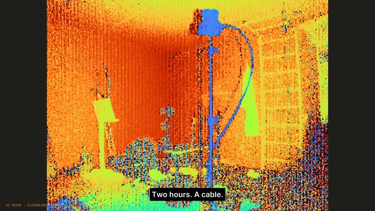
Two hours of software debugging. One cable.
Episode 14 starts with a specification and ends with live points on the desk. In between, the agent worked through the protocol and built the SDK on Apple Silicon. The sensor appeared to connect, but starting a measurement caused it to brown out. Replacing the cable finally got us past roughly two hours of that loop.
This is why I want the bring-up in the story. A simulated sensor has an ideal power supply, a cooperative interface and a tidy stream. Real hardware asks whether it can stay powered during a measurement and whether the receiver recognises a broken packet.
Once the stream worked, RGB registration became the next obstacle. Automatic feature matching failed. A landmark-based loop improved the reported error from 12.7 to 4.56 pixels. The later review used book captures at about 1.92 m and 1.24 m together with stationary room features, with separate held-out landmarks.
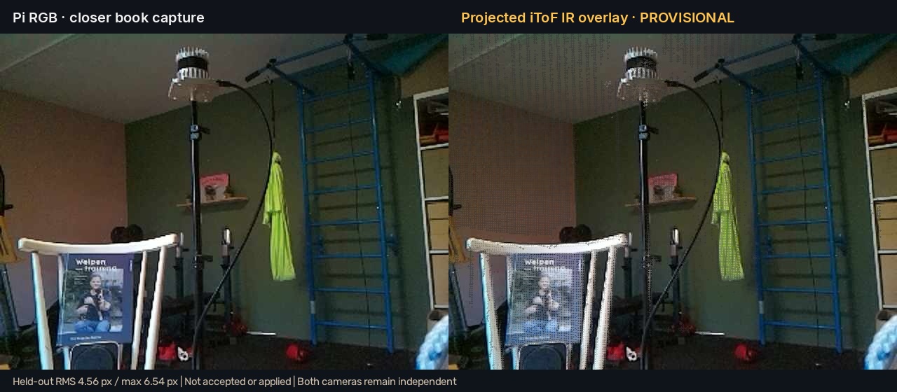
Our acceptance rule required RMS below 4 pixels and every held-out error below 6 pixels. We missed both. Some landmarks had manual localisation uncertainty; the Pi intrinsics were provisionally reused from the earlier camera calibration. This was progress, but it was not an accepted calibration.
A 30-second recording and voxel map made the missing pieces visible again: a rigid mounting relationship, a shared timebase, an IMU and calibration that travels with the device. Software pairing of independent streams is not the same as synchronised exposure.
Less noise. Still a bent wall.
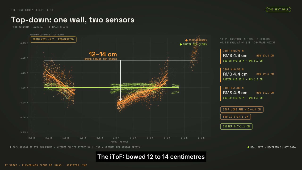
Episode 15 is where a cleaner point cloud stopped being a satisfying result. Across a roughly four-and-a-half-metre wall, the iToF data bowed 12–14 cm towards me. The Ouster comparison showed the wall as straight.
In our exposure test, increasing integration from 500 to 2,000 µs reduced raw jitter from 85 to 28 mm and filtered jitter from 65 to 6 mm. Coverage increased from 35% to 53%. But 8.9% of samples reached the ADC rail. That trade-off matters: quieter output alone does not establish a better measurement.
The receiver also needed three fixes: packet-length checking, rejecting corrupted frames instead of presenting them as fresh data, and byte resynchronisation. We investigated the filter, exposure, lens model, viewer projection and factory correction tables. Three modulation frequencies still returned 4.14 m, 3.92 m and 3.97 m for the same wall.
A fitted correction reduced plane RMS from 4.45 to 1.84 cm on that wall at roughly four metres. It was a fit to one case. It did not demonstrate correct depth at other ranges or on other materials. Mixed pixels, lens spill and cyclic “wiggling” error remained candidate explanations, pending a range sweep and a spill test.
That reopened the dToF route for a wrist camera. The TMF8829 is a different compromise in resolution and range, not a demonstrated cure for every iToF problem. The head-to-head test was still ahead of us at this snapshot.
The one-box idea grew into Mini-X.
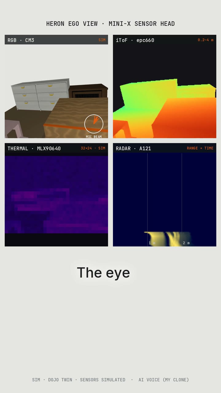
In the parallel design work, the sensor became an action-camera-sized concept: a 62 × 46 × 36 mm enclosure with RGB, iToF, thermal, radar, an IMU and stereo microphones. It is also the proposed eye in Heron’s head.
The proposed layout uses Camera Module 3 for RGB, epc660 iToF with an M12 lens and illumination windows, MLX90640 thermal and A121 radar. An ESP32-P4 architecture was drawn around the camera interfaces, shared frame-sync, storage and power. None of that turns the rendered box into an integrated prototype.
The critical compute question is whether the proposed P4 setup can sustain the MIPI CSI camera and parallel DVP depth input together. That concurrency needs a bench test before PCB layout. The board outlines and component envelopes in the enclosure are approximate; the action-camera mount has not been checked against a real mating part.
The integration discussion moved from dev boards, to a carrier, to a possible chip-down design with separate sensor and main boards. Assembly is only one piece. Optical alignment, illumination, per-pixel and temperature calibration, current camera intrinsics, and independently checked cross-sensor transforms still need to be solved. A shared-clock diagram is a design requirement, not evidence that the real feeds share a clock.
The next useful result is a test that can fail.
I want the next iteration to survive held-out captures, several distances, real motion and repeat mounting. The immediate questions are concrete: does the depth bias change with range; does a lens hood change the wall bow; does the sparse dToF sensor preserve the hand detail the task needs; can the chosen compute ingest both streams reliably?
The attraction of one box is still there. Every frustrating evening with two sensors has made its specification clearer. The product idea is getting better because the experiment keeps refusing to behave like the render.
Evidence: published Episodes 3, 4, 8, 10, 14 and 15; the 20 October calibration review; Mini-X design discussion through 22 October. Sensor figures describe the stated captures or simulations. No finished product, manufacturing quote, accepted whole-system calibration or hardware synchronisation is claimed.